Mastering Your Dashboard: VDO Gauge Installation, Calibration & Maintenance Guide
Complete guide to installing, calibrating, and maintaining VDO gauges for accurate readings and long service life. Professional tips for automotive, marine, and industrial applications.
VDO gauges are renowned for their precision and durability, making them a top choice for automotive, marine, and industrial applications. Proper installation, calibration, and maintenance are key to ensuring these instruments provide accurate readings for years to come. This guide will walk you through the best practices for handling your VDO gauges.
Installation Best Practices
1. Choosing the Right Location
**Visibility and Safety:** Mount gauges where they are easily visible without obstructing your view of the road or waterway. Avoid placing them in the deployment area of airbags.
**Clearance:** Ensure there is adequate space behind the dashboard for the gauge housing and wiring. VDO gauges typically require a mounting depth of around 50mm to 110mm depending on the series.
**Mounting Hole:** Use a hole saw of the correct diameter (e.g., 52mm, 85mm, 100mm) for a snug fit. If the hole is slightly too small, use a file to carefully enlarge it.
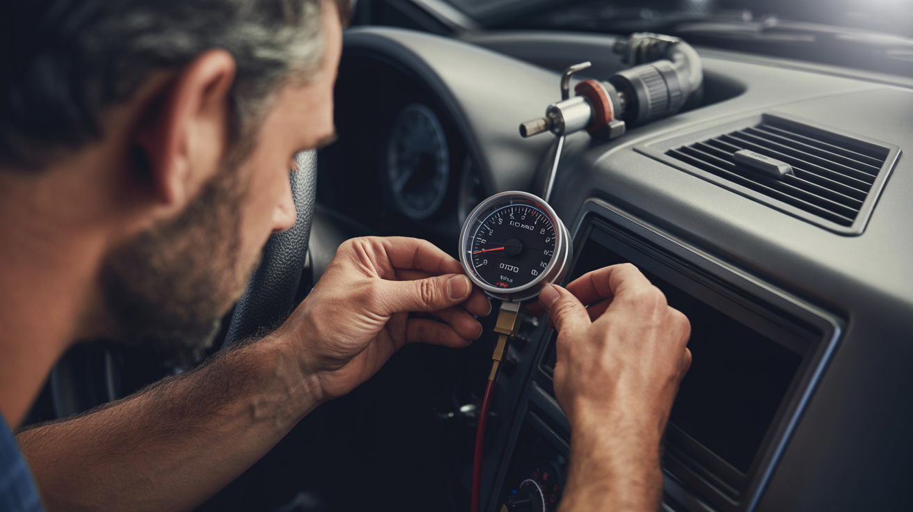
2. Secure Mounting
**Spin-Lok™ Clamp:** Many VDO gauges feature the Spin-Lok™ mounting system, which provides 360 degrees of even clamping force. Tighten the clamp until the gauge is secure and cannot be rotated by hand, but do not overtighten.
**Mounting Bracket:** For gauges with a traditional U-bracket, ensure the bracket is seated correctly and the nuts are tightened evenly.
3. Wiring with Precision
**Disconnect Power:** Before you begin, always disconnect the vehicle's battery to prevent short circuits.
**Power and Ground:** Connect the gauge to a switched 12V or 24V power source (as specified for your gauge) with a 5-amp inline fuse for protection. A solid ground connection is crucial for accurate readings.
**Sender Connection:** Run a dedicated wire from the sender unit to the corresponding terminal on the gauge (often marked 'S' or 'G').
**Illumination:** Connect the gauge's light to the vehicle's dashboard lighting circuit so it illuminates with your other instruments.
**Protect Your Wires:** Use grommets when passing wires through firewalls or bulkheads. Keep wiring away from hot engine components and moving parts. Secure wires with cable ties or loom for a tidy and safe installation.
Calibration for Accuracy
1. Speedometer Calibration
**Automatic Calibration:** Many VDO electronic speedometers feature an "AUTOCL" function. This typically involves driving a measured mile while the speedometer is in calibration mode.
**Manual Calibration:** If you know the pulse-per-mile (PPM) of your vehicle's speed sensor, you can often manually input this value into the speedometer.
**Fine-Tuning:** Some models offer a fine-tuning adjustment to perfectly match a known speed reference, like a GPS-based speedometer app.
2. Tachometer Calibration
**Switch Settings:** Programmable tachometers often have DIP switches on the back to configure them for different engine types (e.g., 4, 6, or 8 cylinders) or alternator pulse signals.
**Potentiometer Adjustment:** For alternator-driven tachometers, a small potentiometer on the back of the gauge allows for fine adjustment to match a reference tachometer.
3. Fuel Level Gauge Calibration
**Sender Matching:** The most critical aspect of fuel gauge accuracy is matching the gauge to the correct sender ohm range (e.g., 240-33 ohms for American vehicles, 10-180 ohms for European vehicles).
**Adjustable Senders:** If you have an adjustable sender, you will need to set the float arm length and swing to match the geometry of your fuel tank.
Troubleshooting Common Issues
**Inaccurate Readings:** The most common cause is a mismatch between the gauge and the sender. Always use the VDO sender designed for your specific gauge. Also, check for a poor ground connection.
**Gauge Not Working:** Check the fuse, power, and ground connections. Ensure the sender wire is securely connected at both ends.
**Pegged Needle:** A needle that immediately goes to the maximum reading often indicates a sender wire that is shorted to ground. A needle that doesn't move at all could be a broken sender wire or a faulty sender.
**Flickering Illumination:** This is usually caused by a loose bulb or a poor connection in the lighting circuit.
Maintenance for Longevity
**Regular Inspection:** Periodically check gauges for any signs of damage, moisture ingress, or loose connections.
**Cleaning:** Clean the gauge lenses with a soft, damp cloth. Avoid harsh chemicals that could damage the plastic.
**Sender Maintenance:** Keep sender units clean and free of debris. For fuel senders in marine applications, inspect for corrosion.
Professional Support
At VDO Parts South Africa, our technical team is available to assist with: - Product selection and compatibility verification - Installation guidance and troubleshooting - Wiring diagrams and technical specifications - Warranty support and replacement parts
**Contact us:** 011 568 9948 | WhatsApp: 084 334 3269
By following these best practices, you can ensure your VDO gauges provide the accurate and reliable information you need to monitor your vehicle's performance and health for years to come.
Need Help with VDO Products?
Our technical team is here to assist with product selection, installation, and troubleshooting